One of the layer two technologies that the CCIE candidate can face is bridging. What bridging does is that it transforms the Router’s behavior of IP routing into a switch like behavior.
The underlying commands are same, they differ when use different modes of Bridging on the router. There are three modes of bridging on Cisco routers. Transparent, Concurrent routing and bridging, and Integrated routing and bridging.
Transparent Bridging
In this mode, the router will behave fully like a bridge (switch). It will no longer be able to do any IP routing operations. This was the legacy mode before newer modes were introduced. The syntax to run this mode is pretty simple.
no ip routing
!
bridge 1 protocol ieee \\ defining the STP protocol to be used for bridging.
!
int fa0/0
ip address 1.1.1.1 255.255.255.0
bridge-group 1
!
int fa0/1
ip address 1.1.1.1 255.255.255.0
bridge-group 1
we can still maintain reachability to the router by assigning an IP address to the bridge interfaces. But remember, the router will never be part of routing domain.
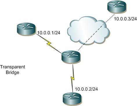
Figure 1: transparent bridging
Concurrent routing and bridging
The transparent bridging has a major limitation. what if my router is connected to both routed domain and bridge domain? It will not work. The solution was a concurrent routing and bridging mode. In this mode, the router will be divided logically into two domains. One part will be of the “ip routing” domain running routing protocols and routed ports, while the second domain is the “bridge”. The syntax is
bridge crb
ip routing
!
bridge 1 protocol ieee \\ defining the STP protocol to be used for bridging.
!
int fa0/0
bridge-group 1
!
int fa0/1
bridge-group 1
Will the router be able to route traffic between the routed and bridge domain? No. It will not. For that, the next mode was introduced.
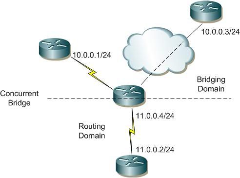
Figure 2: concurrent routing and bridging
Integrated routing and bridging
In this mode, we would have both routing and bridging in one router. We would still be able to route traffic from and to the bridge domain.
The trick in this mode is to create a Bridged virtual interface (BVI). This interface will be used to route traffic from and to the bridged domain. Figure 3 shows the syntax.
bridge crb
ip routing
!
bridge 1 protocol ieee \\ defining the STP protocol to be used for bridging.
!
int fa0/0
bridge-group 1
!
int fa0/1
bridge-group 1
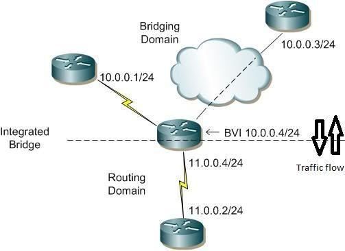
Figure 3: Integrated routing and bridging
There are other variables that can be changed for the bridging operations. But knowing the different kind of modes, how they work, and their limitation is a must know information if you are preparing for CCIE lab exam.


